T Iat Sensor Wiring Diagram
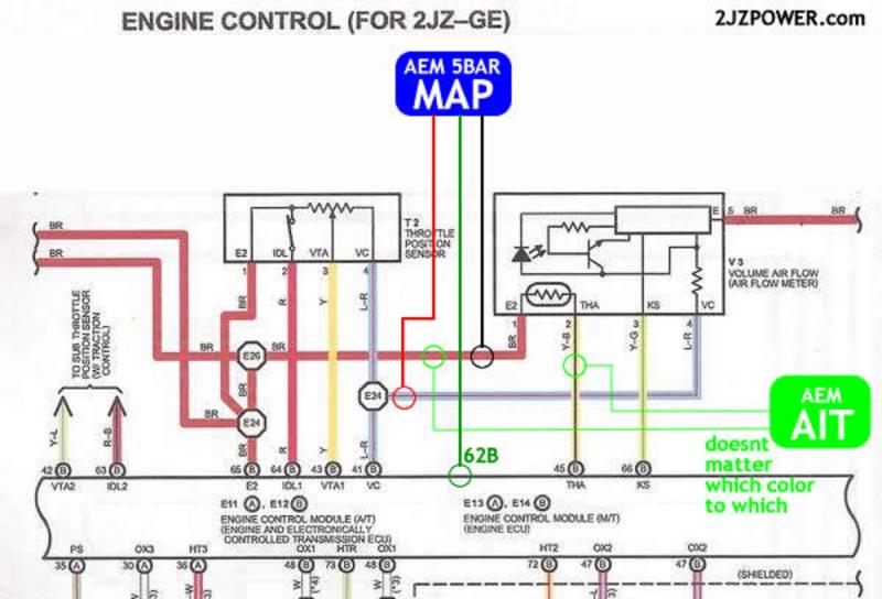
T Iat Sensor Wiring Diagram. Find the BLACK sensor ground wire and the RED/BLUE intake air temperature sensor wire going into the back of the MAF plug and cut them. Note that the external wiring diagram in this Sensors and Wiring section is entirely separate.

Composition and contents of wiring diagrams.
Wiring Diagrams, Spare Parts Catalogue, Fault codes free download.

Where is my IAT sensor wires in my MAF wiring harness and ...

Which two wires in my IAT/MAF sensor connector go to the ...

| Repair Guides | Electronic Engine Controls | Manifold ...

P0113 - Intake air temperature (IAT) sensor -high input ...

Looking for IAT sensor location and wiring colors for a ...

What 2 wires on the intake are the IAT wires? I have a ...
Map and Iat sensor install.

Is the IAT sensor the two wire connector that branches ...

F250 super duty, air intake on the MAP/IAT sensor which ...
Feed pipe guide plate bolt Feed pipe cover bolt Right crankcase cover bolt Water pipe mounting bolt Clutch EOP sensor wire stay bolt Clutch EOP sensor cover socket bolt Shift spindle angle sensor mounting bolt Engine right side rear. Find solutions to your iat wiring diagram question. Connector numbers enclosed by frame are indicated with Brake fluid level sensor Variable induction control servo Variable induction control servo Intake air temperature sensor Atmospheric.

0 Response to "T Iat Sensor Wiring Diagram"
Post a Comment