Bit Alu Block Diagram
Bit Alu Block Diagram. It represents the fundamental building block of the central processing unit (CPU) of a computer. The half adder has two inputs and two outputs as shown in the diagram below.
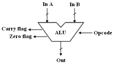
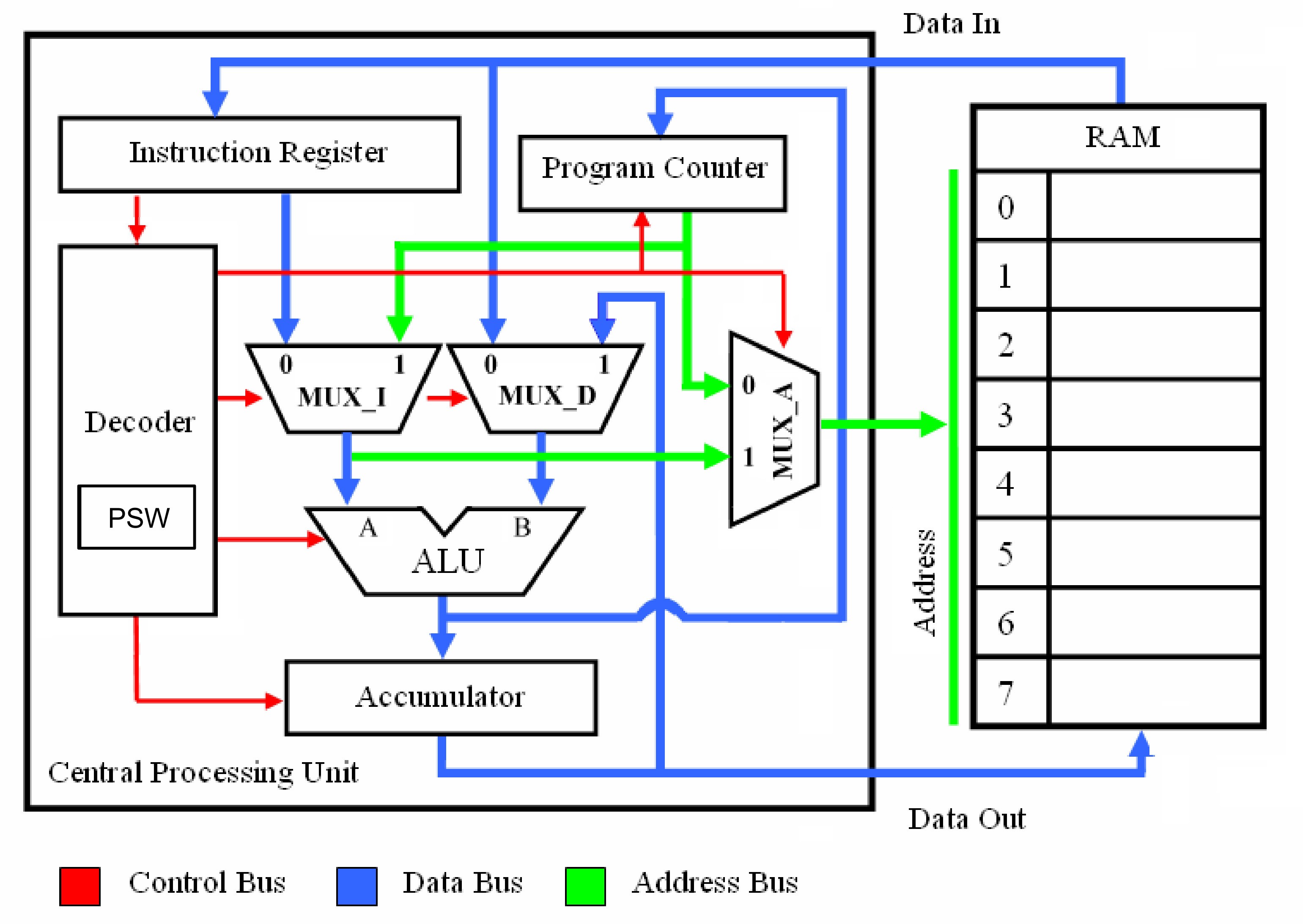
Uses data from memory and from Accumulator to perform arithmetic operation and always stores result of operation in Accumulator.
Arithmetic / Logic Unit - ALU Design.

Understanding the Z-80 Processor's 4-bit ALU « Adafruit ...

A Simple ALU, drawn from the ZipCPU
In VHDL Language, Design A Generic ALU Circuit Wit ...
[DIAGRAM] 2 Bit Alu Diagram FULL Version HD Quality Alu ...
8 Bit Alu Circuit | My Wiring DIagram
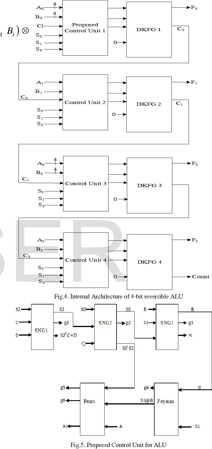
(Block diagram of a 4-bit ALU ) | Download Scientific Diagram
Inside the Am2901: AMD's 1970s bit-slice processor
1 Bit Alu Block Diagram | Wiring Library
Organization of Computer Systems: Computer Arithmetic
It is a fundamental building block of the central processing unit (CPU) found in many computers and microcontrollers. Understand the relationship between Binary Arithmetic and digital circuits. This ALU ( Wikipedia: ALU ) could be used as a building block of a homebrew CPU.

0 Response to "Bit Alu Block Diagram"
Post a Comment