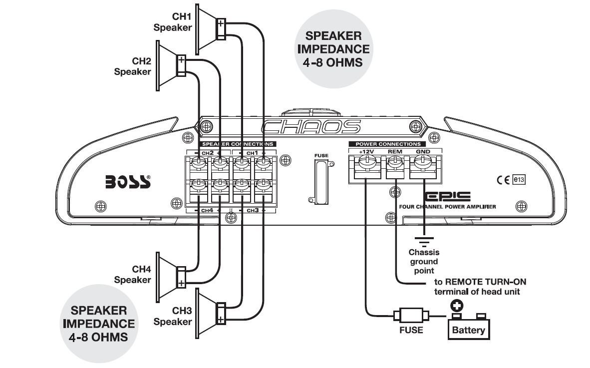
Channel Amplifier Wiring Diagram
Channel Amplifier Wiring Diagram. Amplifier Wiring Diagram Parallel Speaker Channel Amp Wire Connect. Single Phase Capacitor Start-capacitor-run Motor Wiring Diagram.

Note only configurations that provide sufficient power are listed.
As the fastest growing demand of circuit and wiring diagram for automotive and electronics on internet based on different uses such as electronic hobbyists, students.

4 Channel Amp 2 Speaker 1 Sub Wiring Diagram - Wiring ...

Amplifiers - Hybrid Audio Technologies

4 Channels Home Audio Power Amplifier - Electronic Circuit
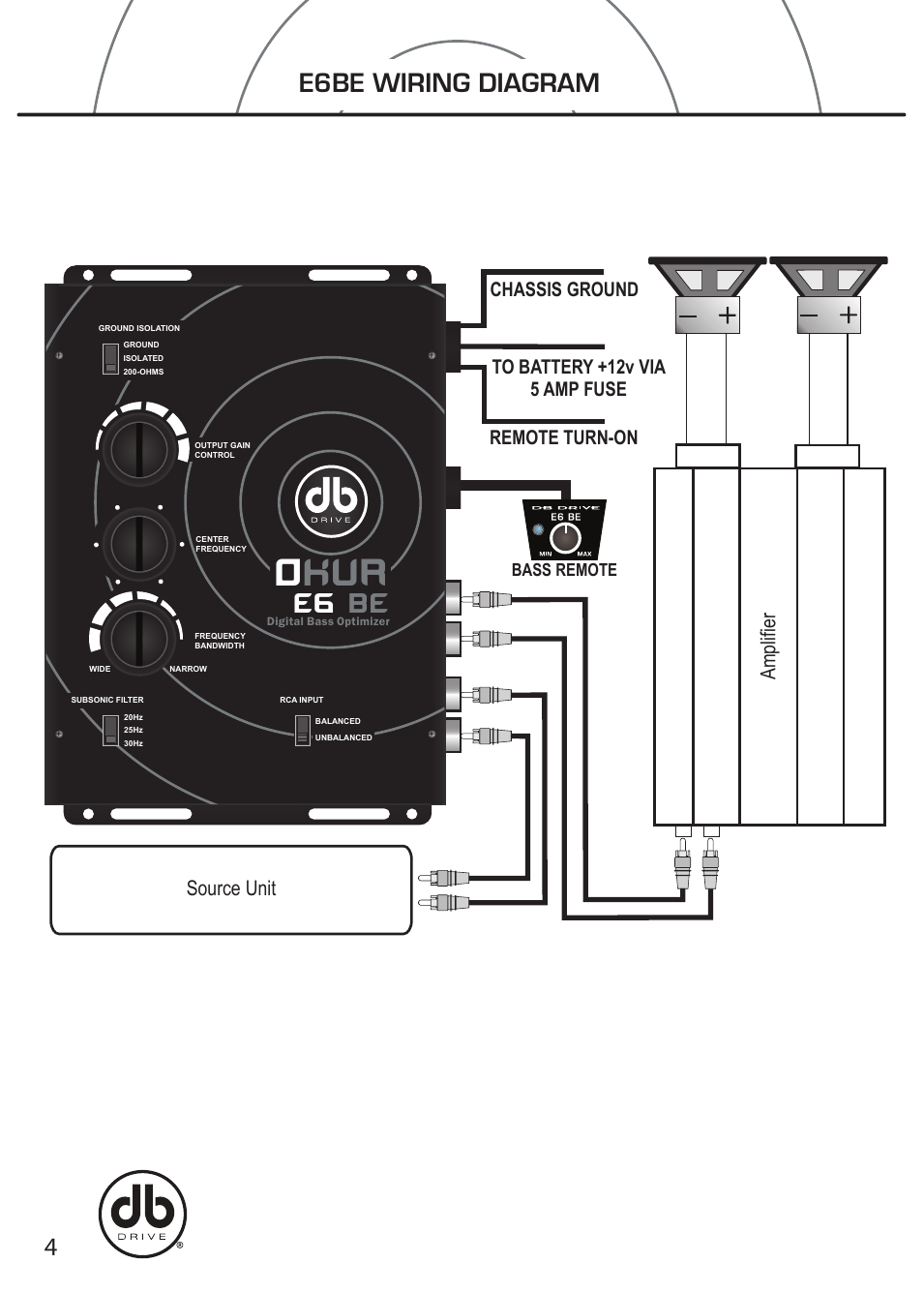
2 Channel Amp Wiring Diagram | Wiring Diagram
Pyle Hydra Amp Wiring Diagram Best Of | Wiring Diagram Image
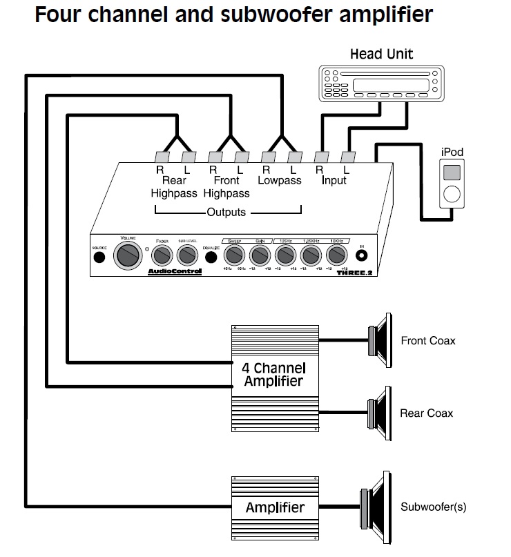
Car Application Diagrams | AudioControl

Subwoofer Wiring Diagram 2 Channel Amp - Doctor Heck

Electro help: Jbl GTH400 - 6/4/3 CHANNEL AUTOMOTIVE POWER ...

INFINITY 5760a - 5761a - 6 CHANNEL POWER AMPLIFIER Wiring ...
One suggestion is to use the amplified As can be seen in the wiring diagram, it is not necessary to use bi-directional Logic Level Digital FM stereo decoder. This explains the color codes and how to hookup an aftermarket amplifier to the factory or aftermarket speakers. The top diagram shows the way in which Fender wires its volume control. (This is the best way to wire a master volume control).

0 Response to "Channel Amplifier Wiring Diagram"
Post a Comment