Bitparator Logic Diagram
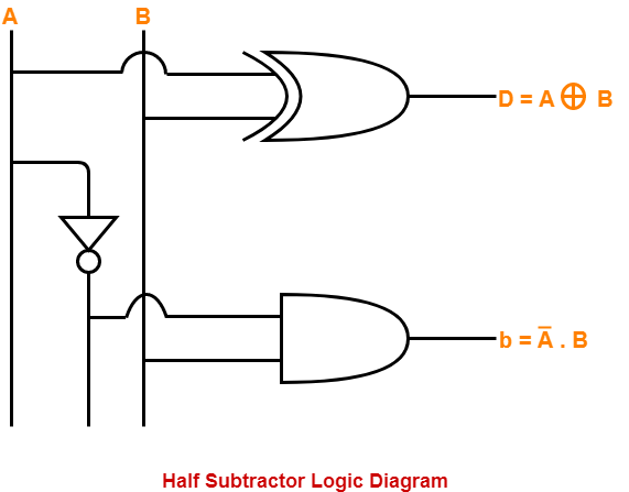
Bitparator Logic Diagram. This page is going to talk about some of the verilog operators. Suppose we want to subtract A & B (i.e.
Now, let's bring in the "extra" features of JavaScript.
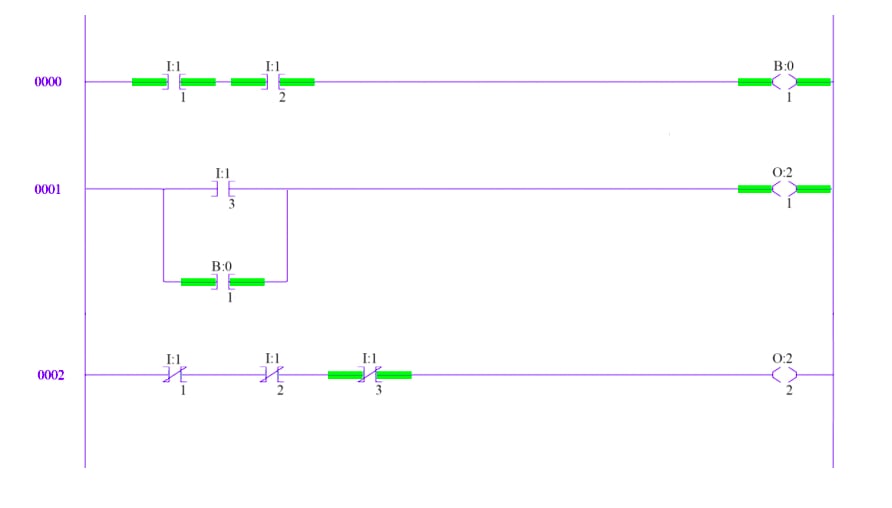
The most basic functionality of a PLC program is logic.
[DIAGRAM] 8 Bitparator Logic Diagram FULL Version HD ...
[DIAGRAM] 8 Bitparator Logic Diagram FULL Version HD ...

Logic diagram of 2 bitparator. The sequence diagram

Diagram based logic diagram of 2 bitparator completed ...
[DIAGRAM] 8 Bitparator Logic Diagram FULL Version HD ...
[DIAGRAM] 8 Bitparator Logic Diagram FULL Version HD ...
[DIAGRAM] 8 Bitparator Logic Diagram FULL Version HD ...
[DIAGRAM] 8 Bitparator Logic Diagram FULL Version HD ...
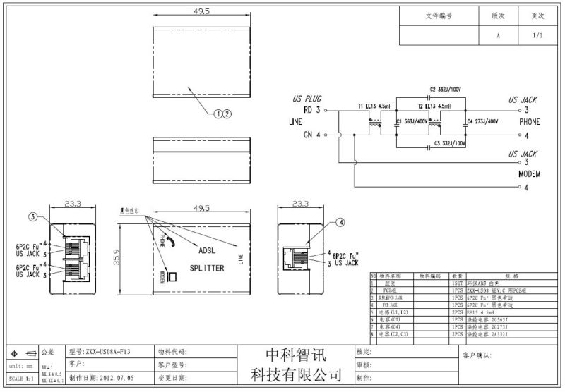
WIRING Cat 3 Wiring Diagram Rj11 HD Version ...
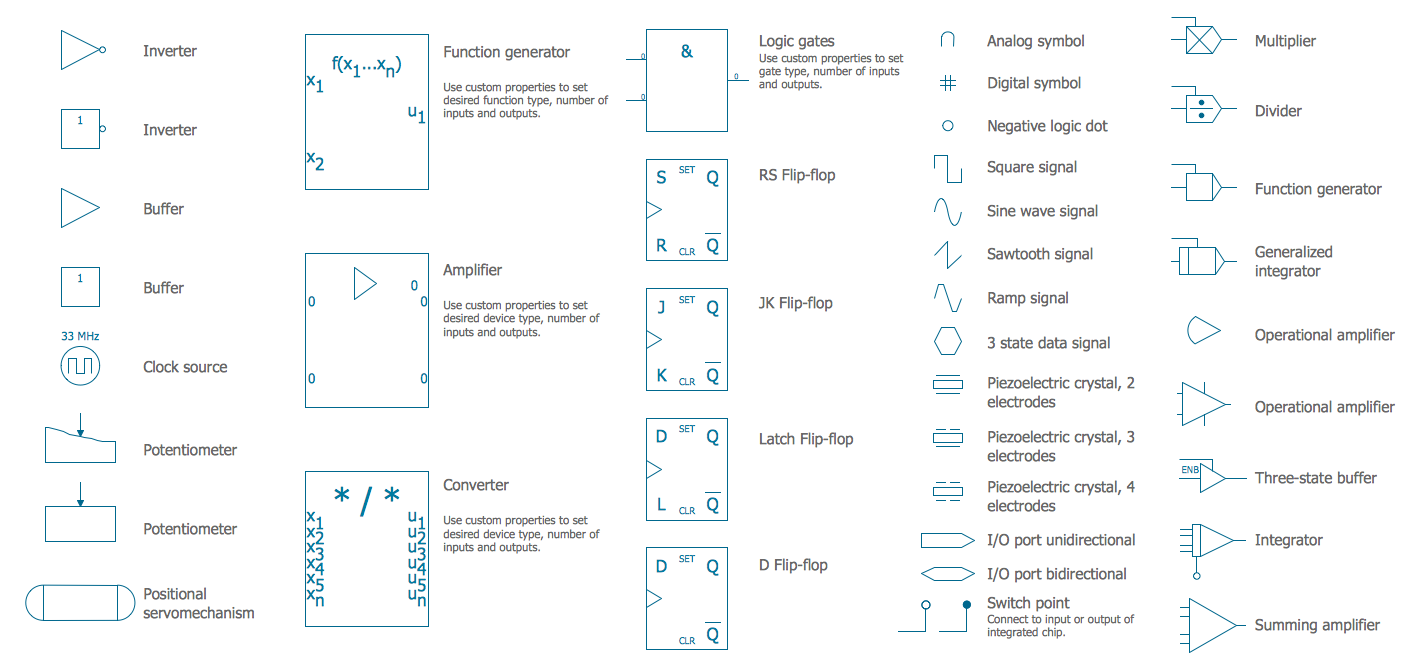
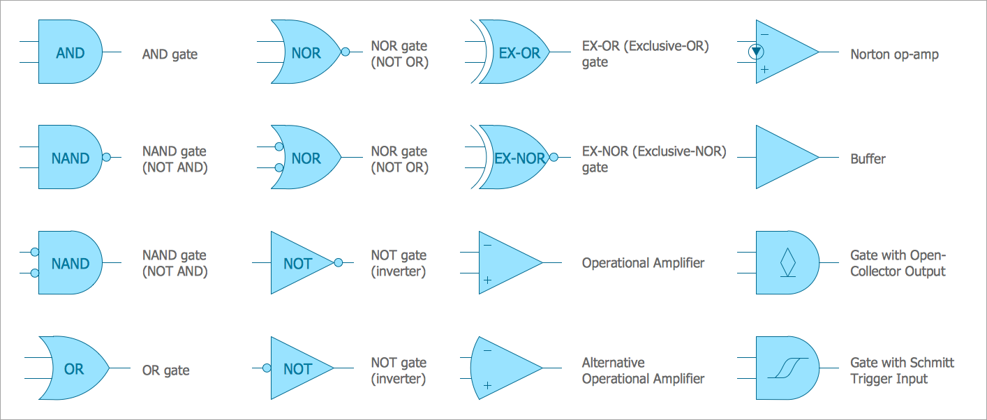
To perform bit-level operations in C programming, bitwise operators are used. Basic logic gate templates to get started fast. The most elementary objects in Ladder Diagram programming are contacts and coils, intended Also Read : Mis-conceptions of PLC Ladder Logic.

0 Response to "Bitparator Logic Diagram"
Post a Comment