Demultiplexer Logic Diagram
Thursday, March 11, 2021
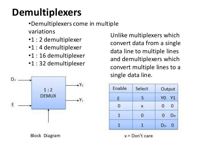
1 to 2 demultiplexer logic diagram,
1 to 4 demultiplexer logic diagram,
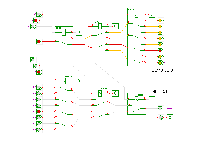
1 to 8 demultiplexer logic diagram,
1-16 demultiplexer logic diagram,
1x4 demultiplexer logic diagram,
demultiplexer logic diagram and truth table
Edit
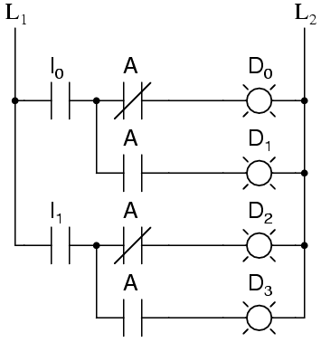
Demultiplexer Logic Diagram. You can see that the enable (we can think of it as the data input for the demultiplexer) feeds into all of the. Below is the logic diagram of the internals of one of the demultiplexers, as we've seen before.

You can see that the enable (we can think of it as the data input for the demultiplexer) feeds into all of the.
Below is the logic diagram of the internals of one of the demultiplexers, as we've seen before.


0 Response to "Demultiplexer Logic Diagram"
Post a Comment